I have made several improvements to the spinning ‘wheel’ since the last post. The major issues that I encountered were that it was spinning much faster than I could draft the fiber, and the pull onto the bobbin was very inconsistent. This made it very difficult to get the approximately fingering weight yarn that I wanted with any consistency. I approached this problem from several angles.
From left to right: braked end of the pulley with nylon brake cord, the maiden, and the drive pulley
Bobbin improvements
made the brake channel wider
made the ends slightly smaller relative to the flyer
Brake improvements
The leather strip I was using was way too sticky and stretchy.
replaced the leather strip with two loops of nylon cord
Drive pulley improvements
increased the size of the drive pulley in order to decrease the amount of spin for the same rate of treadling
With these changes, the consistency of the resulting yarn from inch to inch immediately improved and it was much easier to get the size I intended.
I also added a little hook to the maiden closest to the orifice so that I’d have a place to wrap the live end around to pause it.
Hook with which to pause work
I also purchased some flax fiber to practice on, but I’m waiting to start that until after I’m done with the wool.
All of the wool, first at the top & most recent at the bottom.
Briefly became insane and built a spinning wheel out of a treadle sewing machine base that I bought off of a guy on fb who has a Problem(tm).
I looked up some plans (Etsy), at a bunch of other home builds, and a manufactured one at the local yarn shop Cloverhill. All of this led me to believe that I could Just Build One.
So I did.
Spinning head: user side overview
The main sticking point in most of the designs that I found was needing a lathe to turn pieces. The rest was doing precision woodworking. So I decomposed it into parts that would be hard to make out of wood with the tools that I had, and everything else. I then further broke that category into parts that could be made on a 3D printer and parts that it would be more expedient to buy.
This spinning head is flyer lead (also known as Scotch tension), which means that the flyer is driven and the bobbin is dragged along through friction.
The flyer is composed of – the orifice (printed) – the T (printed) – the arms (cut dowel) – the axle shaft (purchased hex head bolt) – the drive pulley (printed)
The orifice is printed at the highest resolution possible and then smoothed with fine sandpaper on the inside to prevent fiber from catching. It has a snug press fit into the T, but I also glued it in place once I was satisfied with the assembly.
The T has a socket for the axle bolt head, which is a press fit. The arms fit into the ends of the T and are secured with small screws. The arms should be shorter than the bobbin so that the brake line clears the ends.
The drive pulley has a nut that press fits onto. This nut acts like a nylock nut and allows it to drive the axle while making it easy to swap the pulley or bobbin.
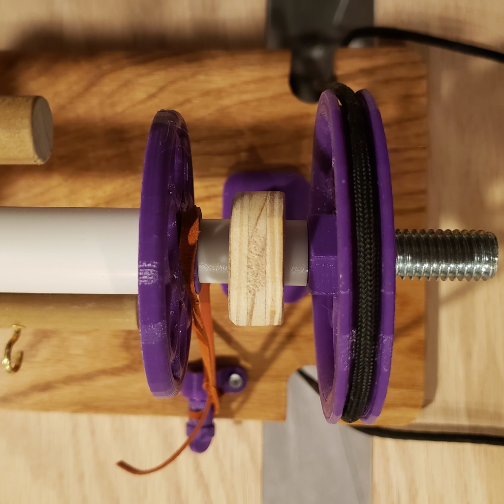
Spinning head: drive pulley, braked bobbin end view
The bobbin is composed of – end piece (printed) – end piece, braked (printed) – PVC tube
The end pieces press fit onto the PVC tube and can be glued. The one with the brake channel should be closest to the pulley when the bobbin is in the machine. The brake ensures that the bobbin spins more slowly than the flyer.
The brake is a thin leather strip threaded through a printed adjustment screw.
Close up of the bobbin and drive pulley showing the loose spacing between the parts
The stand is made out of plywood and aligned with printed brackets. The parts are secured with small screws. One of the maidens (the vertical parts that hold the axle) has a nylon bushing in it to reduce the friction between the threads of the axle and the wood.
I’m not an experienced spinner so I cannot comment on the quality of it relative to manufactured spinning wheels, but it does work. Below, you can see the quality of my spinning going up from left to right as I get the machine tuned and my hands back in practice.
Improved the fold out drawer on the front by slapping some veneer on it and repairing the inside so that it no longer eats (as many) sewing needles and other small objects.
I figured that I couldn’t make the cabinet situation worse and with the back up plan of harvesting a replacement from some other unlucky machine, I decided to start cutting into the cabinet. To do the construction, I got certified to use the wood shop at the local makerspace Openworks.
After analysis, there were a couple types of damage.
Layers of wood delaminated and shifted in relation to each other
wood bent out of alignment from water expansion or weight of the machine
screw holes stripped out
This is a big post covering several months of work, so here’s a readmore to save you the scroll.
Right so as I said in the previous post, the wooden cabinet suffered a lot of water damage. The four screws that hold the base of the lift arm are not in steady wood/the holes are stripped. The hole that the sewing machine comes up through is sufficiently warped that it cannot be lifted through while it is bolted in place. Additionally the sewing machine sits on top of the woodwork and is visibly warping/exacerbating existing damage.
I imagine that the sewing machine is supposed to sit level and even with the table surface. I am not sure that the table surface(s) could be effectively refinished because of the warping and separation. The brass hardware seems to be in good condition. The steel hardware has surface rust.
lift arm
It’s a pretty hefty spring for a pretty heavy machine.
In the above picture, the left corner hits the wood instead of passing by it with close clearance. The sewing machine is supposed to sit on tabs protruding from the panel along the body of the machine- instead it sits on top of that panel.
the wood on the hinge side is also warped
I found a bit of rust inside the machine, but none of it is on bearing surfaces. I’m going to try to remove it and oil the pitting to discourage any further development.
I oiled the belt with boot leather oil and stitched it back into place. The bobbin winder is missing a critical rubber piece, so I wound a bobbin on the Featherweight. Replaced the needle. Adjusted the tension. It sews very nicely. Getting the treadle started is a bit of an adventure but I imagine practice makes perfect and so on. Needle up is wherever all that iron wants it to be.
I am planning pulling out what parts of the mechanism that I can in order to remove the oil varnishing and properly oil and grease all of the bearing surfaces, and try to reduce the needle lift click.
I have a new belt and the piece that the bobbin winder is missing coming in the mail.
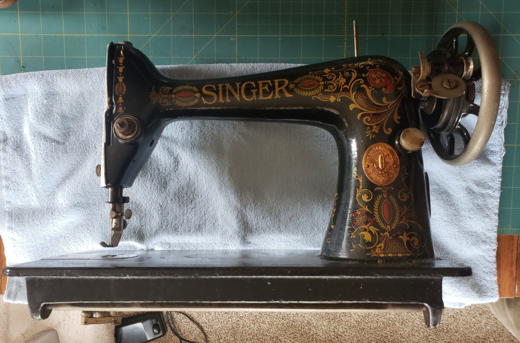
It’s a No. 66 ‘red eye’. I haven’t found a serial number but the manual was printed in 1916.
A quick rundown of what I’ve seen so far:
– The machine itself is in incredibly good condition. The action is smooth and frictionless. There is no rust. The decals are in nearly perfect condition. The bobbin race turns, the bobbin comes out, and the bobbin eject mechanism works perfectly. There’s a fair bit of oil varnishing but none of it appears to be impacting function. I’m planning on cleaning that up and oiling it. It looks like it uses a standard bobbin size.
– Hurricane Agnes did a number on the cabinet. It is largely constructed out of plywood and every piece that could delaminate has tried to delaminate. The varnish and stain are rough/cracked. The locks are rusted in place (although I do have the key). The bottoms of all four drawers are separated. The block of wood that holds the lift arm and spring is cracked where the screws are. I can’t get at it right now so I can’t guess if it’s repairable/replaceable. There is however no rot in the wood.
-All of the accessories that were in the drawers have spot rust and are responding well to a de-rust bath.
– The cast iron base/stand is in excellent condition. The little rolly feet all roll. The treadle mechanics are smooth. All I’m planning there is a touch of oil.
– I had to cut the belt to separate the cabinet and the stand to get it into the car. The belt is leather and is in actually very good condition (much better than the ‘spare’ in the cabinet, which looks like it might have been the original and was stuck in the envelope that the replacement came in). I am planning on using the good leather oil on it to supple it up again and then sewing it back together when I know what size it needs to be. The original closure was a staple, so I know what level of workmanship I need to apply here.
At this point I think I need an experienced opinion on whether the cabinet should (could?) be restored or if measurements should be taken and more or less built new. Consider that the lid on it would look really nice in a light/dark stripe pattern, and if it was done with a 1/4 or 1/2 inch spacing, it could also work as a layout guide.