
Briefly became insane and built a spinning wheel out of a treadle sewing machine base that I bought off of a guy on fb who has a Problem(tm).
I looked up some plans (Etsy), at a bunch of other home builds, and a manufactured one at the local yarn shop Cloverhill. All of this led me to believe that I could Just Build One.
So I did.
The main sticking point in most of the designs that I found was needing a lathe to turn pieces. The rest was doing precision woodworking. So I decomposed it into parts that would be hard to make out of wood with the tools that I had, and everything else. I then further broke that category into parts that could be made on a 3D printer and parts that it would be more expedient to buy.
And then I got modeling. You can find my repo and BOM here.
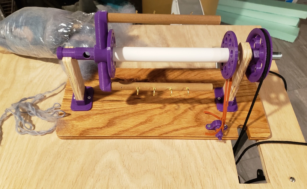
This spinning head is flyer lead (also known as Scotch tension), which means that the flyer is driven and the bobbin is dragged along through friction.
The flyer is composed of
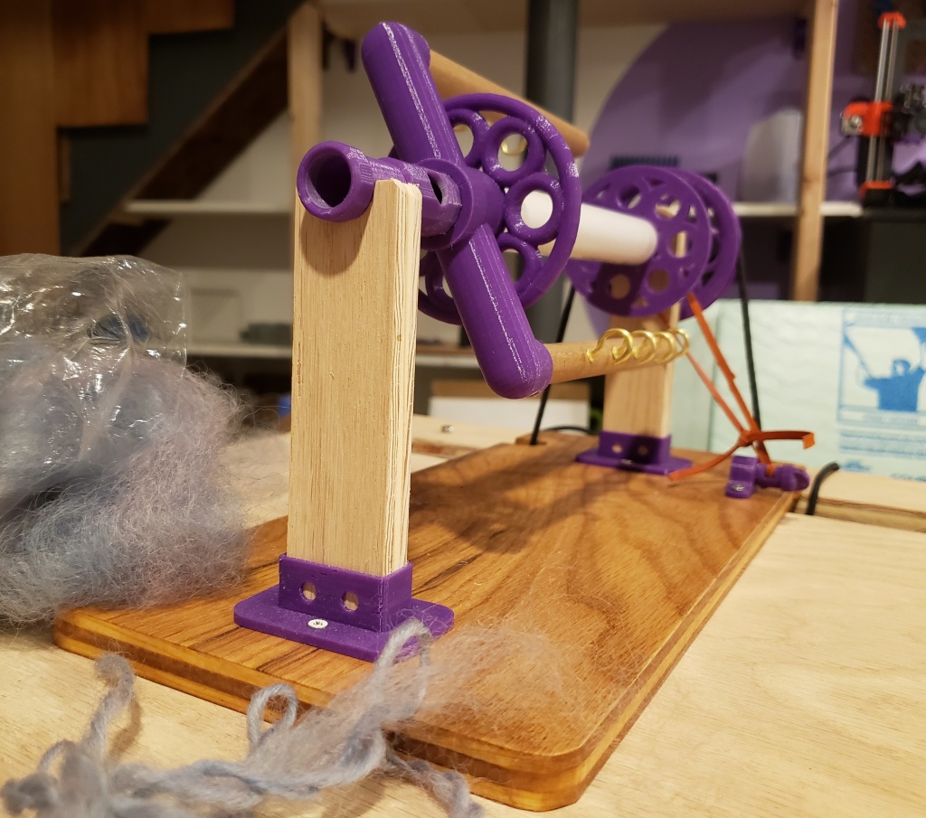
– the orifice (printed)
– the T (printed)
– the arms (cut dowel)
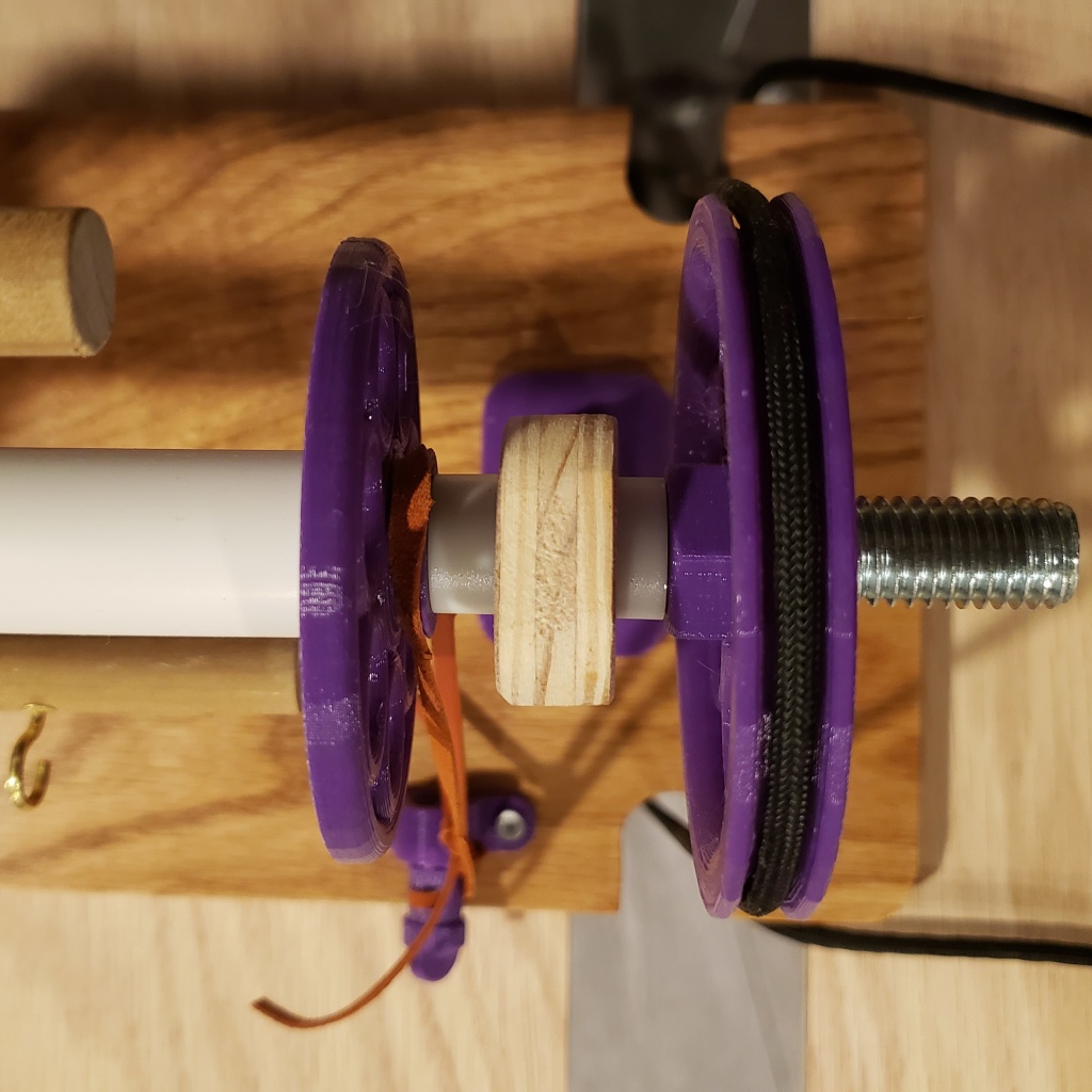
– the axle shaft (purchased hex head bolt)
– the drive pulley (printed)
The orifice is printed at the highest resolution possible and then smoothed with fine sandpaper on the inside to prevent fiber from catching. It has a snug press fit into the T, but I also glued it in place once I was satisfied with the assembly.
The T has a socket for the axle bolt head, which is a press fit. The arms fit into the ends of the T and are secured with small screws. The arms should be shorter than the bobbin so that the brake line clears the ends.
The drive pulley has a nut that press fits onto. This nut acts like a nylock nut and allows it to drive the axle while making it easy to swap the pulley or bobbin.

The bobbin is composed of
– end piece (printed)
– end piece, braked (printed)
– PVC tube
The end pieces press fit onto the PVC tube and can be glued. The one with the brake channel should be closest to the pulley when the bobbin is in the machine. The brake ensures that the bobbin spins more slowly than the flyer.
The brake is a thin leather strip threaded through a printed adjustment screw.
The stand is made out of plywood and aligned with printed brackets. The parts are secured with small screws. One of the maidens (the vertical parts that hold the axle) has a nylon bushing in it to reduce the friction between the threads of the axle and the wood.
I’m not an experienced spinner so I cannot comment on the quality of it relative to manufactured spinning wheels, but it does work. Below, you can see the quality of my spinning going up from left to right as I get the machine tuned and my hands back in practice.

